

robotics-university.com | Hello my friends, hope all of you always in good condition. Today, I will guide you to build the first LabVIEW application project that implement LabVIEW Interface for Arduino (LIFA) toolkit that we had been installed on Virtual Intrument Package Manager (VIPM). I have explained about the steps on my previoous article, please click here!
A. Hardware - Arduino & LED Circuits
Below is the circuits of a Light Emitting Diode (LED) component that connected on the fourth pin of Arduino Uno board. See figure 1!

Figure 1. Arduino Uno & LED circuits
In order we can control the LED, connect the Arduino board via USB port to a computer (PC/Laptop) that LabVIEW and LIFA toolkit has been installed on that. See figure 2!

Figure 2. LabVIEW, LIFA, and Arduino Uno board
B. Program Descriptions
For this project, we have to create a LabVIEW graphical program that has purpose to control LED (ON/OFF) condition. If a Light Emitting Diode (LED) component that connect to a selected Arduino pin (in this project I use fourth pin. See figure 1) set to one (HIGH logic) using "Digital Write Pin" LIFA object, the LED on that pin will light up (ON condition), vice-versa, if selected Arduino pin set to zero (LOW logic), the LED will in OFF condition.
C. Text-based Program
If we create a text-based program to control LED (ON/OFF) condition with follow the program description on B point above. The program is as shown on the figure 3 below. I type that code on Arduino IDE software.

Figure 3. Arduino text-based program typed on Arduino IDE
The program will make the LED on the Arduino fourth pin in light up (ON condition) when the LED variable equal to one (HIGH logic), vice-versa, the LED will in OFF condition when the LED variable equal to zero (LOW logic).
D. Graphical Program on LabVIEW Block Diagram
If we want to control the LED (ON/OFF) condition using LabVIEW, We can’t using text-based programming, but we have to create a graphical program. With follow the program description on B point above, we can create graphical program as shown on the figure 4 below (See figure 4). The graphical program on figure 4 represented text-based program on figure 3. So if we run the both program, they will have same output, i.e. output signal to control LED (ON/OFF) condition.

Figure 4. LabVIEW graphical program using LIFA toolkit
Table 1. Used LIFA object
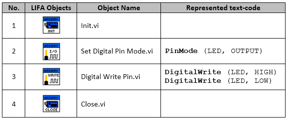
If we see on figure 4, that graphical program using four LIFA objects, i.e. “Init” object, “Set Digital Pin Mode” object, “Write Digital Pin” object, and “Close” object (See Table 1). In order, we can create a complete and right LabVIEW graphical program, we have to know the descriptions of each LIFA object that used. To do that, we can see the object description of each “Context Help” window.
Context Help
If you want to know the description of an object which you want to use it when create a LabVIEW graphical program, you can use “Show Context Help” option to do that. To start use the option, on Block Diagram window, click Help menu, then select “Show Context Help” option or you can use shortcut key “Ctrl + H.” See figure 5!

Figure 5. Step to Show Context Help
After you select “Show Context Help” option, then left-click an object to open a “Context Help” window of the object. Once you click an object, the descriptions of the clicked object will show on its context help window. On this example, the descriptions of “Init” object, “Set Digital Pin Mode” object, “Write Digital Pin” object, and “Close” object shown on Figure 6, Figure 7, Figure 8, and Figure 9.

Figure 6. Click “Init” object to open its context help window

Figure 7. Click “Set Digital Pin Mode” object to open its context help window

Figure 8. Click “Digital Write Pin” object to open its context help window

Figure 9. Click “Close” object to open its context help window
Create Your Own LabVIEW Graphical Program
To start create your own LabVIEW graphical program, you can follow my example LabVIEW graphical program on Figure 4. For your information, when create a LabVIEW graphical program using LIFA toolkit, we have to start the program with “Init” object (Init.vi) and with “Close” object (Close.vi) for the ending.
E. Graphical User Interface on LabVIEW Front Panel
Figure 10, show to us a Graphic User Interface (GUI) application that automatically created on LabVIEW Front Panel window when we create graphical program on LabVIEW Block Diagram window.

Figure 10. GUI to control LED (ON/OFF) condition
The main part of the GUI on Figure 10, is a “STOP” button and a “Numeric Control.” Stop button use to stop program looping (on this example, While Loop), in order the program stop running. While “Numeric Control” use to set the pin-value (0 logic or 1 logic) of “Digital Write Pin” object.
F. LabVIEW Project - Complete
Figure 11, show to us an image of a complete LabVIEW project using LIFA toolkit package. There are displayed the Project Explorer window, the Front Panel window, and the Block Diagram window.

Figure 11. LabVIEW project - GUI on Front Panel & Graphical Program on Block Diagram
G. Run the Graphical Program
To start running our LabVIEW application that we have created, click on “Run” button (See figure 12), either “Run” button on Front Panel tool-bar or “Run” button on Block Diagram tool-bar.
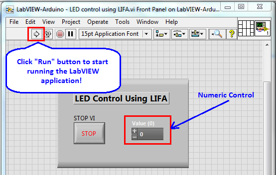
Figure 12. Click “Run” button to start running LabVIEW application
Then see on the Arduino board, the LED on fourth-pin will be in ON condition if on the Numeric Control, we set the value is one (1, High logic) and will be in OFF condition if we set the value is zero (0, Low logic). See figure 12.
________________________________
Note:
If you face errors when you follow my guidance to
create LabVIEW project using LIFA toolkit, I recommend you to read article
entitled “LabVIEW Interface for Arduino Error 5002: Unable to EstablishConnection”
0 comments:
Post a Comment